
 PDF Index
| SDT-piezo
Contents
Functions
PDF Index |
The automated procedure requires the plate model to be defined in mm. In order to add the patches, one needs to make a structure which contains the initial plate model and a description of the different patches to be added.
In this example, the patches are assigned with
+Rect.Sonox_P502_iso.5525TH0_25 where the sign +/- specifies if the patch is on the top (+) or the bottom (-) of the plate, the first argument gives the geometry (Rect for Rectangular), the second argument is the
piezoelectric material type from the database, the next argument is the size (55mm x 25mm here) and the last argument is the thickness (0.25mm).
So the first step  d_piezo('TutoPzMeshingAuto-s1')
is to make the host plate. Here, we define a mesh so that the edges of the piezoelectric patches will correspond to the mesh (as in the previous example of meshing manually).
d_piezo('TutoPzMeshingAuto-s1')
is to make the host plate. Here, we define a mesh so that the edges of the piezoelectric patches will correspond to the mesh (as in the previous example of meshing manually).
Then in d_piezo('TutoPzMeshingAuto-s2')
we add four rectangular piezoelectric patches whose size and shape comply with the mesh.
%% Step 2: Add patches
RG.list={'Name','Lam','shape'
   'Main_plate', model,''  % Base structure
   'Act1', ... % name of patch
   'BaseId1 -Rect.Sonox_P502_iso.5525TH0_25 +Rect.Sonox_P502_iso.5525TH0_25', ...
     struct('shape','LsRect', ... % Remeshing strategy (lsutil rect here)
       'xc',15+55/2,'yc',12+25/2,'alpha',0,'tolE',.1)
    'Act2', ... % name of patch
   'BaseId1 -Rect.Sonox_P502_iso.5525TH0_25 +Rect.Sonox_P502_iso.5525TH0_25', ...
     struct('shape','LsRect', ... % Remeshing strategy (lsutil rect here)
       'xc',15+55/2,'yc',63+25/2,'alpha',0,'tolE',.1)
       };
mo1=d_piezo('MeshPlate',RG);
mo1=stack_rm(mo1,'info','Electrodes'); % Obsolete stack field to be removed
% To avoid warning due to the use of simplified piezo properties.
mo1=p_piezo('DToSimple',mo1);
The command +Rect.Sonox_P502_iso.5525TH0_25 refers to a patch which is added on the top of the plate (+), is rectangular (Rect), is made of Sonox_P502_iso, is of size 55mm x 25mm (5525) and thickness 0.25 mm (TH0_25).
Then we need to specify the position of the patch with 'xc' and 'yc' which correspond to the coordinates of its center.
The model obtained is here the same as the one previously obtained with manual meshing. The static response when actuating the first piezo patch is computed in d_piezo('TutoPzMeshingAuto-s3')
. The value of the tip displacement is
d1t = 2.5244e-09
Note that the automated meshing introduces the patches in the order of the description, so that here the first piezoelectric patch is on the bottom (-), and the static response is downwards, as in the case of manual meshing. This allows to compared the displacement at the tip which has the same value (2.52 µ m / V).
Automated meshing can also be done when the patch edges do not coincide with the mesh of the host plate. In this case, automated local remeshing is applied around the patches inserted. In d_piezo('TutoPzMeshingAuto-s4')
we take the example of an initial mesh of the plate with a uniform mesh of prescribed element size (here around 7 mm). The script to add the four patches is strictly identical, but the result is different due to the local remeshing.
The uniform mesh is generated with
%% Step 4 : use local remeshing element size is 7 mm
 model=feutil('objectquad 1 1',[0 0 0;1 0 0;0 1 0], ...
    feutil('refineline 7',[0 463]), ...
    feutil('refineline 7',[0 100]));
     model.unit='mm';
The values of d1t and d2t correspond to the tip displacement when actuating the first piezo patch, for the first model where the edges of the piezos correspond to the element sides in the mesh, and when there is a local remeshing. Due to the effect of the local remeshing (Figure 5.4), there is a slight difference (≈ 1%). The values of tip displacement with the two different meshes are:
d1t = 2.5244e-09
d2t = 2.4901e-09
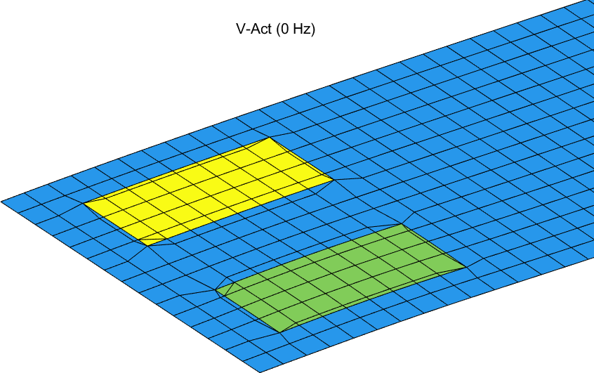
Figure 5.4: Static response to a unit voltage application on one of the bottom piezoelectric patches
In d_piezo('TutoPzMeshingAuto-s5')
, in order to check this effect, we can use a finer mesh of the host structure and check for the convergence.
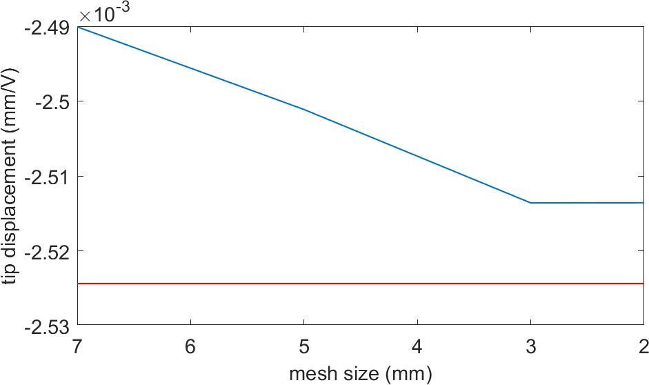
Figure 5.5: Convergence of the tip displacement when the size of the elements of the main plate is varied, using local remeshing. The red line corresponds to the tip displacement with the mesh conforming with the patch edges
We see that when the plate mesh is finer (Figure 5.5), the local effect of remeshing is less and we converge to the tip displacement when the piezoelectric patch edges coincide with the mesh.
A last example in d_piezo('TutoPzMeshingAuto-s6')
is the addition of circular patches, where we also check for convergence. The introduction of circular patches is done with the arguments -Disk.Sonox_P502_iso.RC10TH0_25 and +Disk.Sonox_P502_iso.RC10TH0_25 which specifies a disk made of Sonox_P502_iso material with a radius RC of 10mm and a thickness TH of 0.25 mm (same thickness as the rectangular patches).
The circular patches are introduced with the following syntax:
RG.list={'Name','Lam','shape'
   'Main_plate', model,''  % Base structure
   'Act1', ... % name of patch
   'BaseId1 -Disk.Sonox_P502_iso.RC10TH0_25 +Disk.Sonox_P502_iso.RC10TH0_25', ...
   struct('shape','lscirc','xc',15+55/2,'yc',12+25/2),
   'Act2', ... % name of patch
   'BaseId1 -Disk.Sonox_P502_iso.RC10TH0_25 +Disk.Sonox_P502_iso.RC10TH0_25', ...
   struct('shape','lscirc','xc',15+55/2,'yc',63+25/2)};
The local remeshing can be see in Figure 5.6.
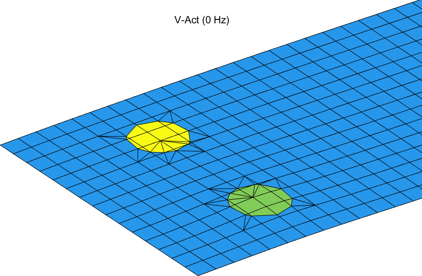
Figure 5.6: Static response to a unit voltage application on one of the bottom circular piezoelectric patches
The last step d_piezo('TutoPzMeshingAuto-s7')
allows to check convergence as for the rectangular patches with automated meshing.
The convergence of the tip displacement can be see in Figure 5.7. Note that the tip displacement is about 5 times smaller than with the rectangular patches, which is mainly due to the circular shape (less efficient than the rectangular shape for plate bending).
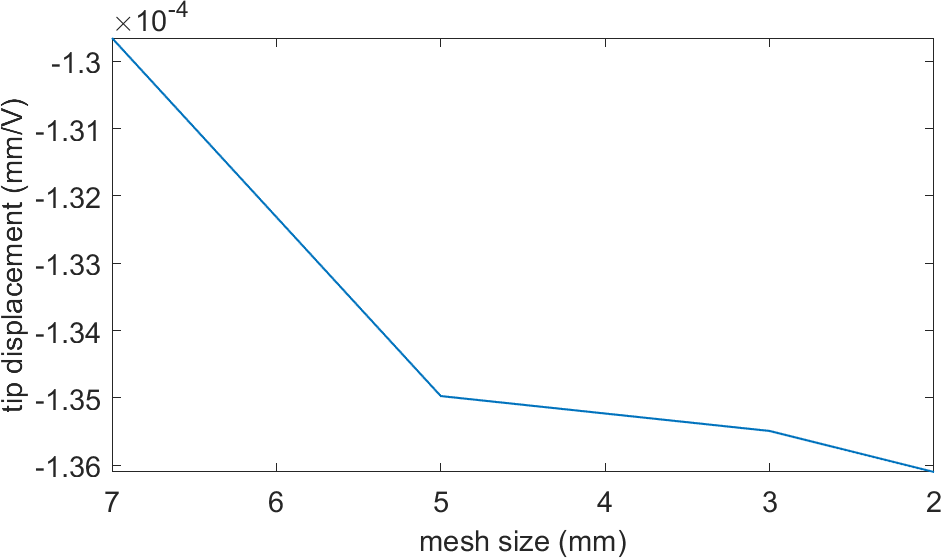
Figure 5.7: Convergence of the tip displacement when the size of the elements of the main plate is varied, for a circular piezoelectric patch
