
 PDF Index
| SDT-base
Contents
Functions
PDF Index |
Purpose
GMSH interface. You can download GMSH at http://www.geuz.org/gmsh/ and tell where to find GMSH using
Syntax
setpref('OpenFEM','gmsh','/path_to_binary/gmsh.exe') % Config
model=fe_gmsh(command,model,...)
model=fe_gmsh('write -run','FileName.stl')
Description
The main operation is the automatic meshing of surfaces. To create a simple mesh from a CAD file (.stp, .igs,...), a dedicated Tab has been built to do it using GUI.
Open the GMSH tab, shown in figure 10.3 with the command
cf=feplot(5);
fecom(cf,'initGMSH');
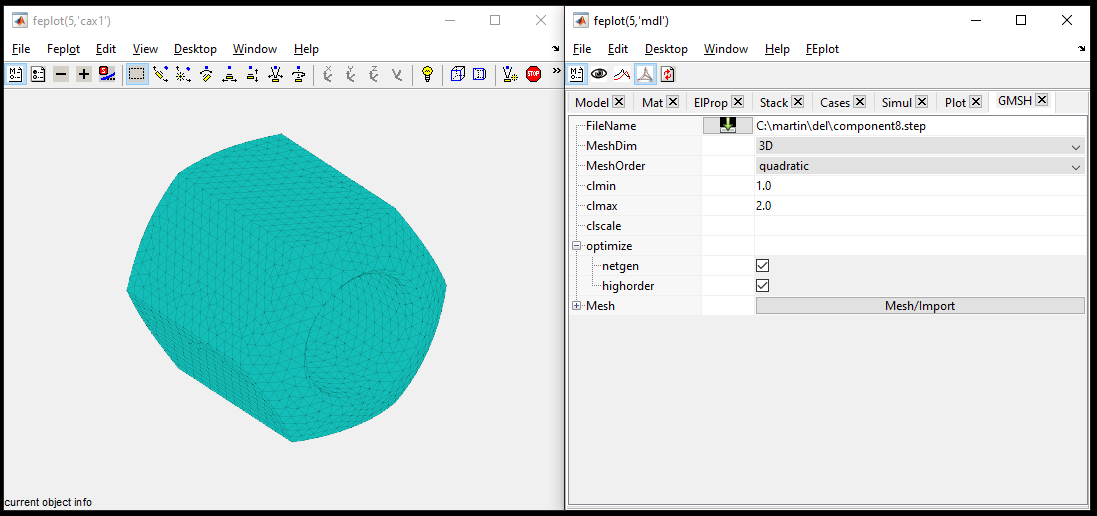
Figure 10.3: GMSH Tab and mesh result
Please find below the description of each parameter
When clicking on Mesh, the equivalent command line call is displayed in the console if you need to redo this from script.
This example illustrates the automatic meshing of a plate
 FEnode = [1 0 0 0  0 0 0; 2 0 0 0  1 0 0; 3 0 0 0  0 2 0];
 femesh('objectholeinplate 1 2 3 .5 .5 3 4 4');
 model=femesh('model0');
 model.Elt=feutil('selelt seledge ',model);
 model.Node=feutil('getnode groupall',model);
 model=fe_gmsh('addline',model,'groupall');
 model.Node(:,4)=0; % reset default length
 mo1=fe_gmsh('write del.geo -lc .3 -run -2 -v 0',model);
 feplot(mo1)
This other example makes a circular hole in a plate
% Hole in plate :
model=feutil('Objectquad 1 1',[0 0 0; 1 0 0;1 1 0;0 1 0],1,1); %
model=fe_gmsh('addline -loop1',model,[1 2; 2 4]);
model=fe_gmsh('addline -loop1',model,[4 3; 3 1]);
model=fe_gmsh('AddFullCircle -loop2',model,[.5 .5 0; .4 .5 0; 0 0 1]);

model.Stack{end}.PlaneSurface=[1 2];
mo1=fe_gmsh('write del.geo -lc .02 -run -2 -v 0',model)
feplot(mo1)
To allow automated running of GMSH from MATLAB, this function uses a info,GMSH stack entry with the following fields
| .Line | one line per row referencing NodeId. Can be defined using addline commands. |
| .Circle | define properties of circles. |
| .LineLoop | rows define a closed line as combination of elementary lines. Values are row indices in the .Line field. One can also define LineLoop from circle arcs (or mixed arcs and lines) using a cell array whose each row describes a lineloop as {'LineType',LineInd,...} where LineType can be Circle or Line and LineInd row indices in corresponding .Line or .Circle field. |
| .TransfiniteLines | Defines lines which seeding is controlled. |
| .PlaneSurface | rows define surfaces as a combination of line loops, values are row indices in the .LineLoop field. Negative values are used to reverse the line orientation. 1st column describes the exterior contour, and followings the interiors to be removed. As .PlaneSurface is a matrix, extra columns can be filled by zeros. |
| .EmbeddedLines | define line indices which do not define mesh contours but add additional constrains to the final mesh (see Line In Surface in the gmsh documentation. |
| .SurfaceLoop | rows define a closed surface as combination of elementary surfaces. Values are row indices in the .PlaneSurface field. |
The local mesh size is defined at nodes by GMSH. This is stored in column 4 of the model.Node. Command option -lcval in the command resets the value val for all nodes that do not have a prior value.
Typical calls are of the form [mdl,RO]=fe_gmsh('Add Cmd',mdl,data). The optional second output argument can be used to obtain additional information like the LoopInfo. Accepted command options are
data can also be a 2 by 3 matrix defining the coordinates of the 2 extremities.
data can also be a string defining a line selection.
The fe_gmsh function uses the OpenFEM preference to launch the GMSH mesher.
setpref('OpenFEM','gmsh','$HOME_GMSH/gmsh.exe')
Command Ver returns the version of gmsh, the version is transformed into a double to simplify hierarchy handling (e.g. version 2.5.1 is transformed into 251). This command also provides a good test to check your gmsh setup as the output will be empty if gmsh could not be found.
fe_gmsh('read FileName.msh') reads a mesh from the GMSH output format. Starting with GMSH 4 .msh is an hybrid between mesh and CAD so that direct reading is not possible. You should then use an extention .ext field to force GMSH to export to a format that SDT supports ()
fe_gmsh('write FileName.geo',model); writes a model (.Node, .Elt) and geometry data in model.Stack'info','GMSH' into a .geo file which root name is specified as FileName (if you use del.geo the file is deleted on exit).
All text after the -run is propagated to GMSH, see sample options below.
It also possible to add a different output file name NewFile.msh, using model=fe_gmsh('write NewFile.msh -run','FileName.stl').
Known options for the run are
From a geometry file the simplest meshing call is illustrated below
 filename=demosdt('download-back http://www.sdtools.com/contrib/component8.step')
 RO=struct( ... % Predefine materials
   'pl',m_elastic('dbval -unit TM 1 steel'), ...
   'ext','.msh', ... % Select output format by extension (use .m MATLAB for GMSH>4)
   'sel','selelt eltname tetra10', ... % Elements to retain at end
   'Run','-3 -order 2 -clmax 3 -clmin 2 -v 0');  %RunCommand
  model=fe_gmsh('write',filename,RO);
It is also possible to write GMSH post-processing command lines, written at the end of the file (see the GMSH documentation) by providing a cell array (one cell by command line) in the field .Post of the RO structure.
See also
missread
