
SDTools regularly performs Experimental Modal Analyses (EMA) in an oven to control temperature dependency. One of the objectives of such test is to identify the constitutive properties of various systems:
- 3D woven composites
- Tuned-mass dampers
- Polymer materials
- …
From the EMA, an inverse problem can be resolved to minimize the error between a model synthetizing the constitutive law parameters and the experimental results, as part of the model updating techniques available at SDTools.
The key to constitutive law parameter identification is to design an experiment that generates a sufficient deformation in the associated directions of work. Exploiting structural modes allows an optimal ratio between energy input and deformation amplitude.
For this application, the sample must thus be placed in the oven with the following constraints:
- Mode shapes of interest must lie in a target frequency band
👉 Tune boundary conditions: connection of the sample to an inertial base - Isolate the system from the oven structure to avoid measurement pollution
👉 Suspend the base over springs - Fit in the oven
👉 It is kind of obvious, but this limits the base size (dimension and weight) - Be of a reasonable price
Regularly, a large base weight is required for the mode shapes of interest to be low enough in frequency, but it needs to be tuned as function of the sample. We have thus decided to build our own evolutive inertial base for such use cases.
Below is the story of the conception of this base divided in two main steps:
1️⃣ Inertial base design with FEM to check technical specifications
2️⃣ Inertial base building
I – Inertial base design with FEM to check technical specifications
The inertial base technical specifications are set up using simulation-based estimations. A very simple geometry is defined, considering the constraints.
From our past measurement campaigns and our oven characteristics, the following specs are derived
- 300mm width and 300mm depth
👉 Oven fitting constraint: with a 600×1000 width and depth frame, we want to ensure comfortable handling in the oven. - Base mass < 20kg
👉 The base must be handled by a single person. - Up to 100kg
👉 Possibility to add weights to the base side for tunability, once in position. - No deformation mode below 500Hz (base fitted with 4 weights of 10kg)
👉 Aluminum beam truss to balance rigidity and mass limit.
👉 Compact structure: it will be a 300mm cube shape.
Considering cost and optimal rigidity, the aluminum beam profiles are chosen to be the standard EU norm of 40x40mm².
From this initial concept a model can be built to refine the design. Using the beam properties provided by the manufacturer, a cube shaped of 300mm edge truss is defined. The first mode is estimated at 637Hz.
Fastening features must then be added. We should be able to add weights around the cube sides (as bodybuilding training weights) so that a fastener at the middle of the faces is required. We also need fasteners to connect the system on the base top, and to suspend the whole with supporting springs.
Beam crosses are thus added to each cube face, leading to an increase of the first mode frequency at 1204Hz.
We then add 4 punctual masses at the middle of each side to coarsely represent the addition of 4*10 kg. The first mode shape is now down to 415Hz, below the 500Hz specifications.
To increase the first mode frequency, beams are placed inside the cube to constraint the observed breathing pattern, resulting in a frequency of 627Hz.
This refined concept meets the specifications it is retained for a physical build.
II – Inertial base building
From the model, the base device is built from
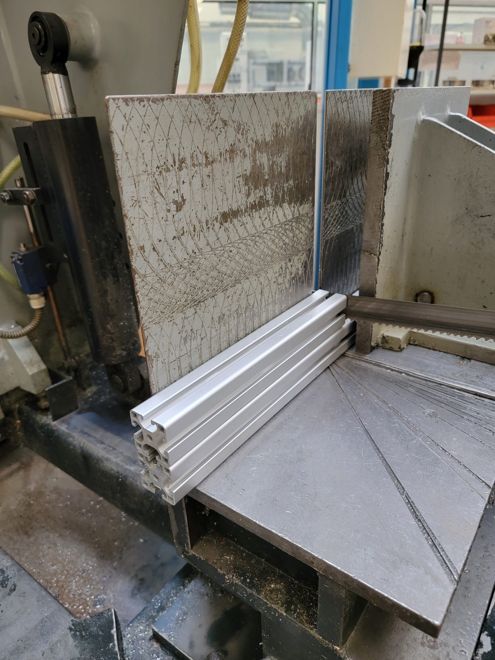
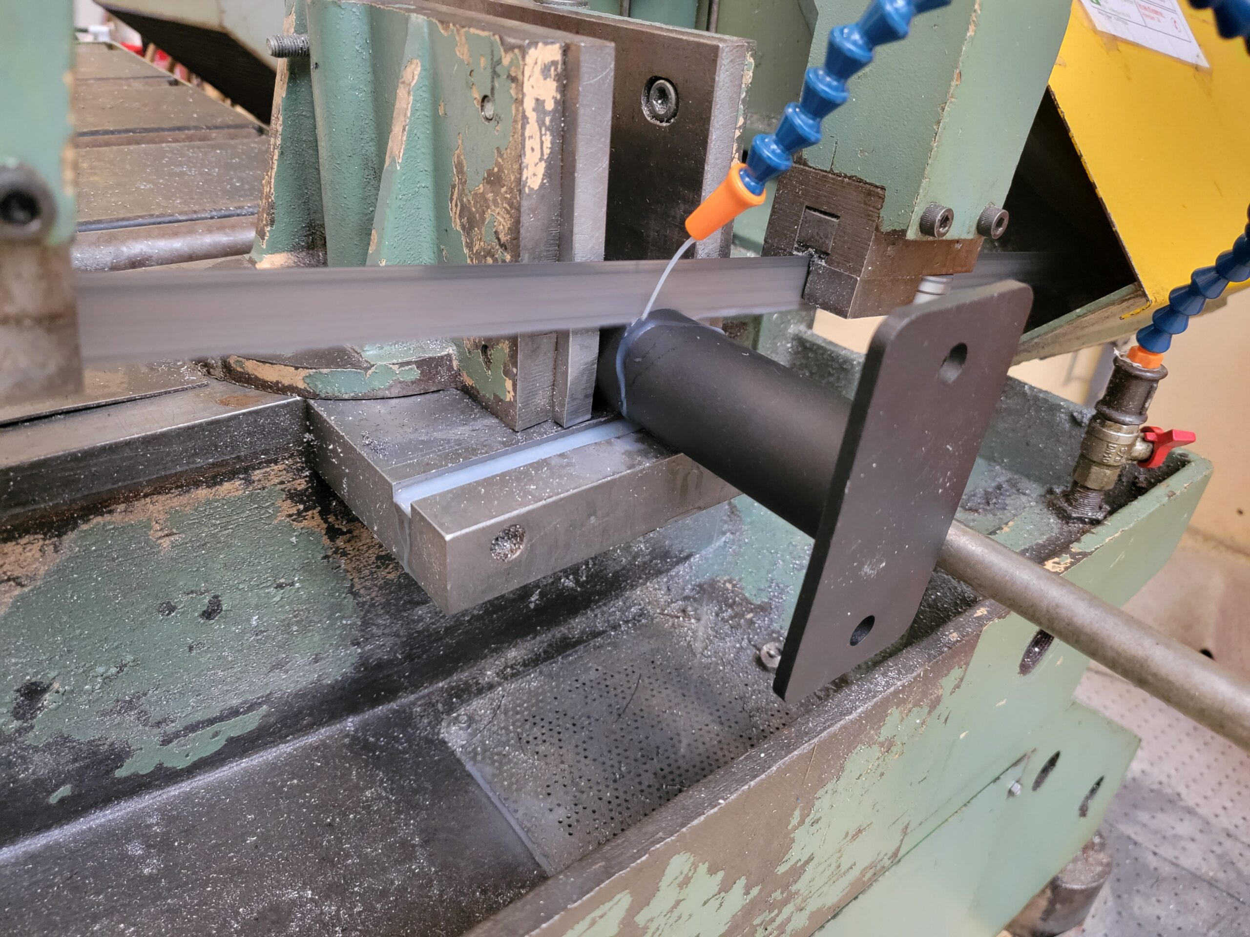
- Saw-cut aluminum profile sections (40 x 40 mm²) for the base truss
- 4 x 300
- 15 x 220
- 16 x 90
- 144 x 90° angle brackets (beam connectors)
- 432 x M8 nuts + bolts
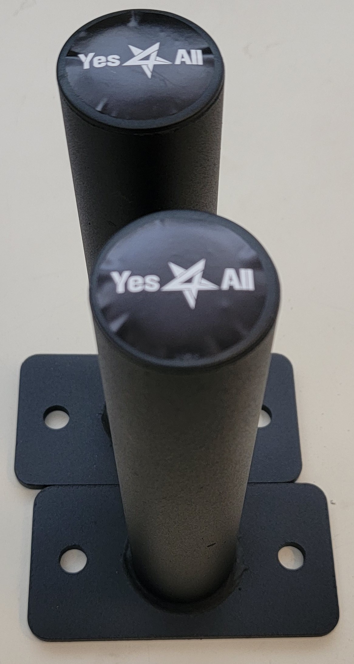
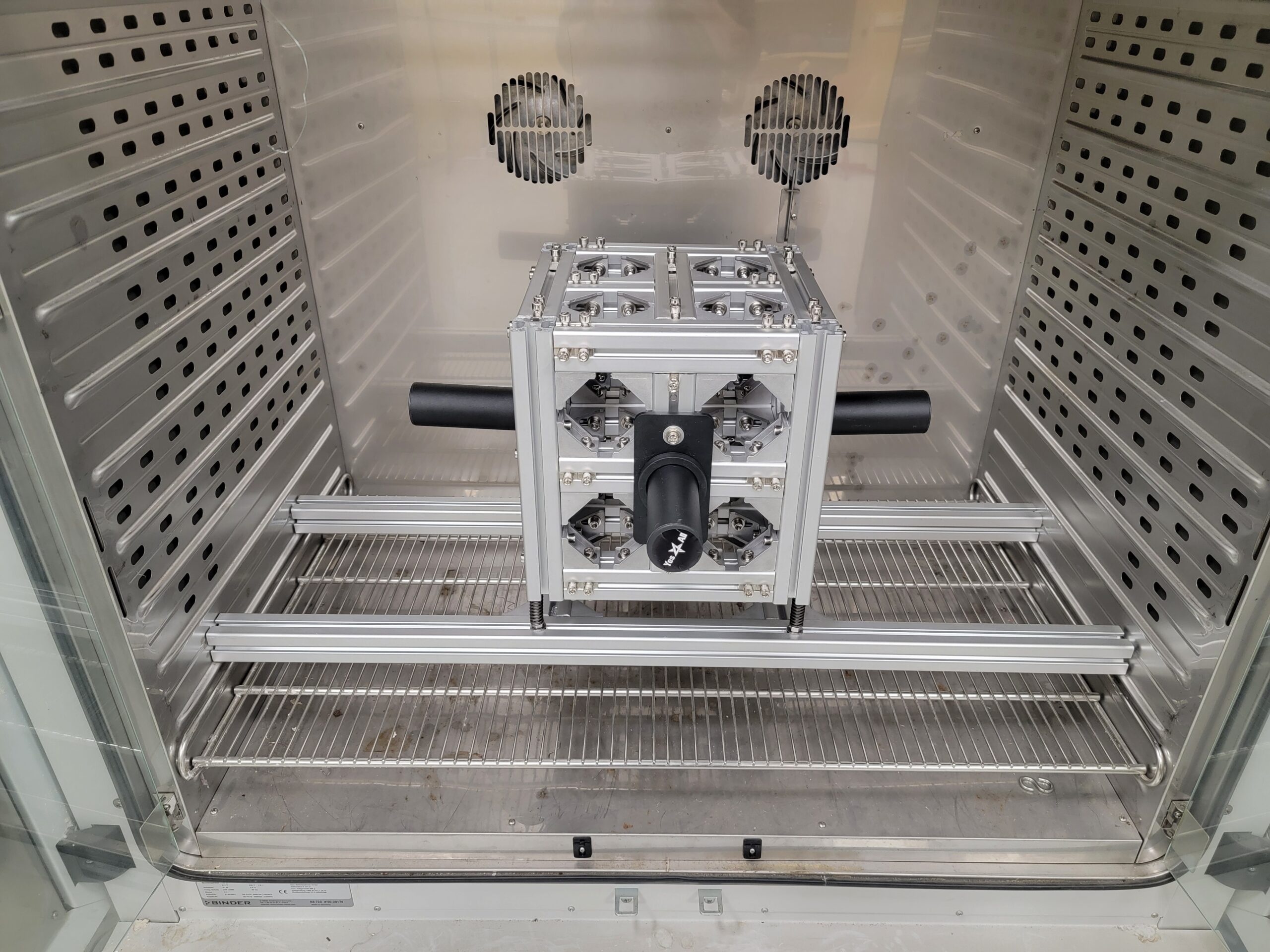
- 4 x training weight holders for walls
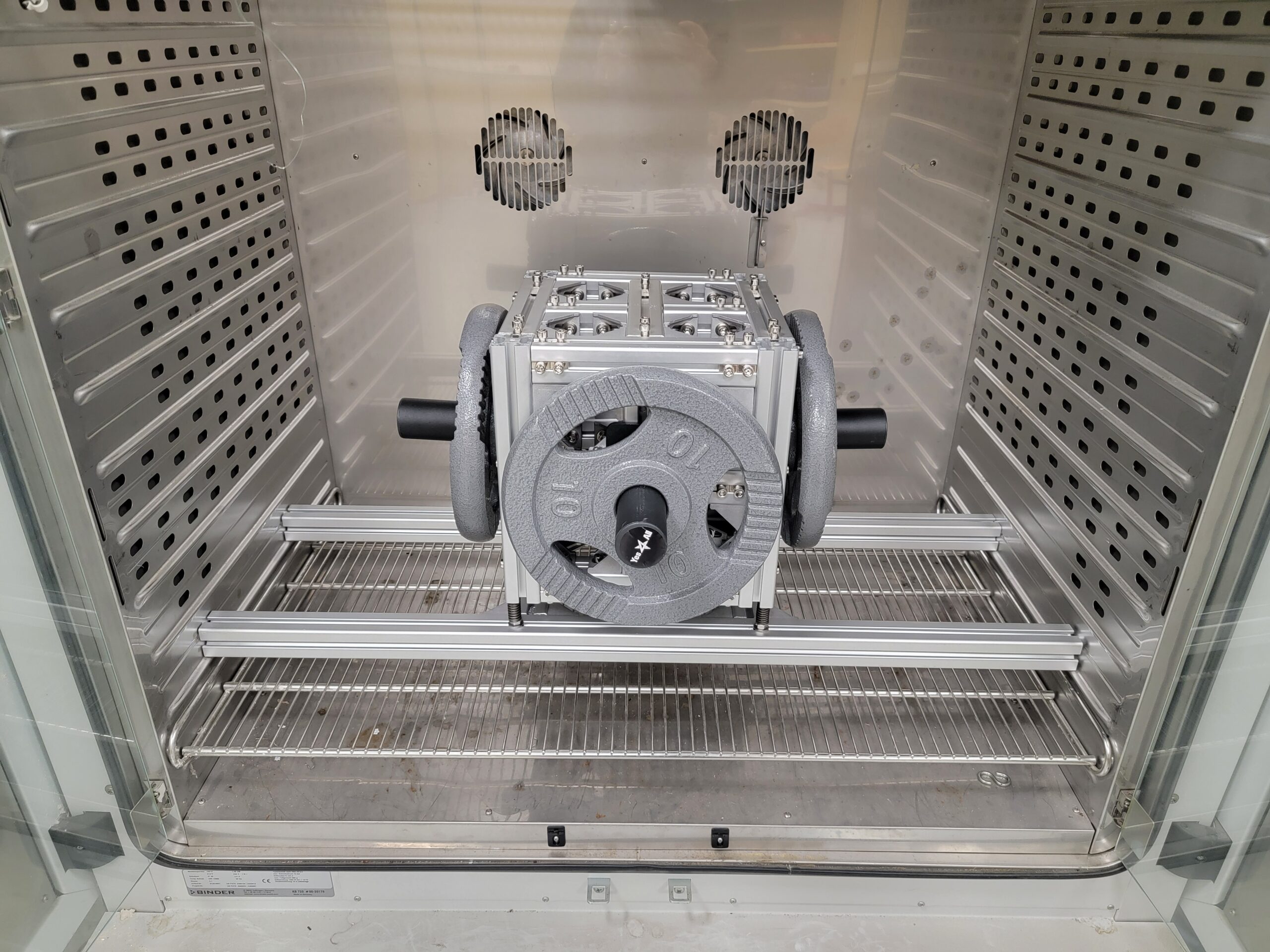
- 4 x 10 kg training weight discs
Below are the main building steps :
1️⃣ Cut everything (beams, weight wall supports)
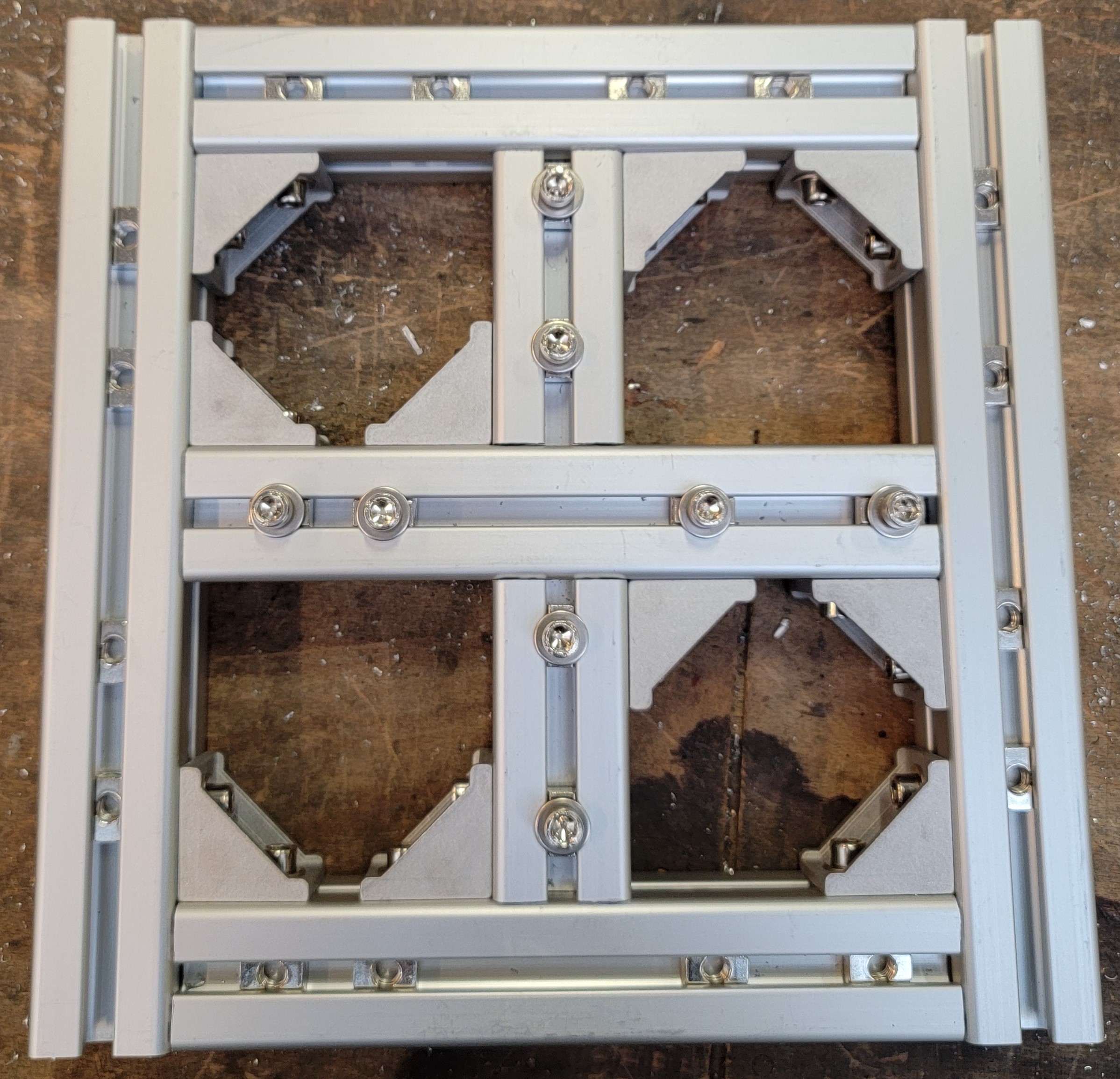
2️⃣ Build the first face
Place 4 x M8 nuts in each beam:
- On the inside of the cube: to be connected to other beams through brackets
- On the outside of the cube: to open connection for evolutions, as port to connect body training weight discs, further base modifications, base suspensions, system clamping to the base…
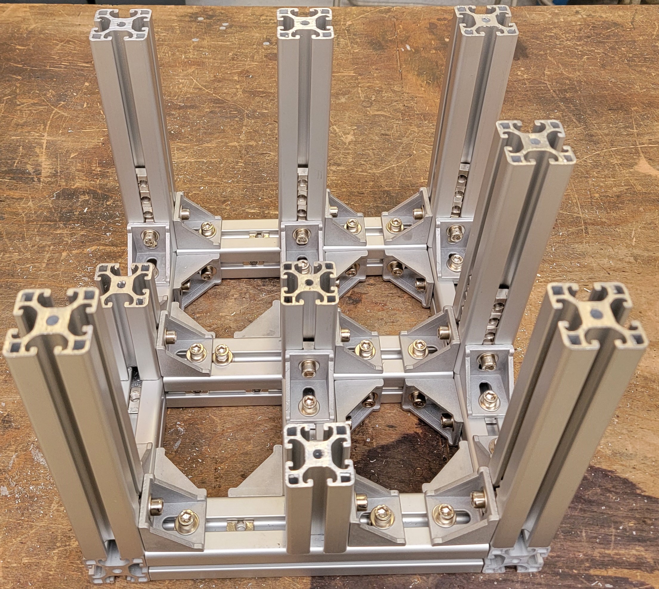
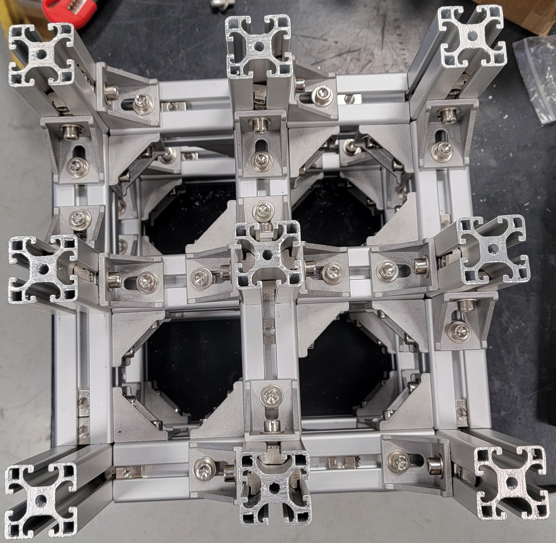
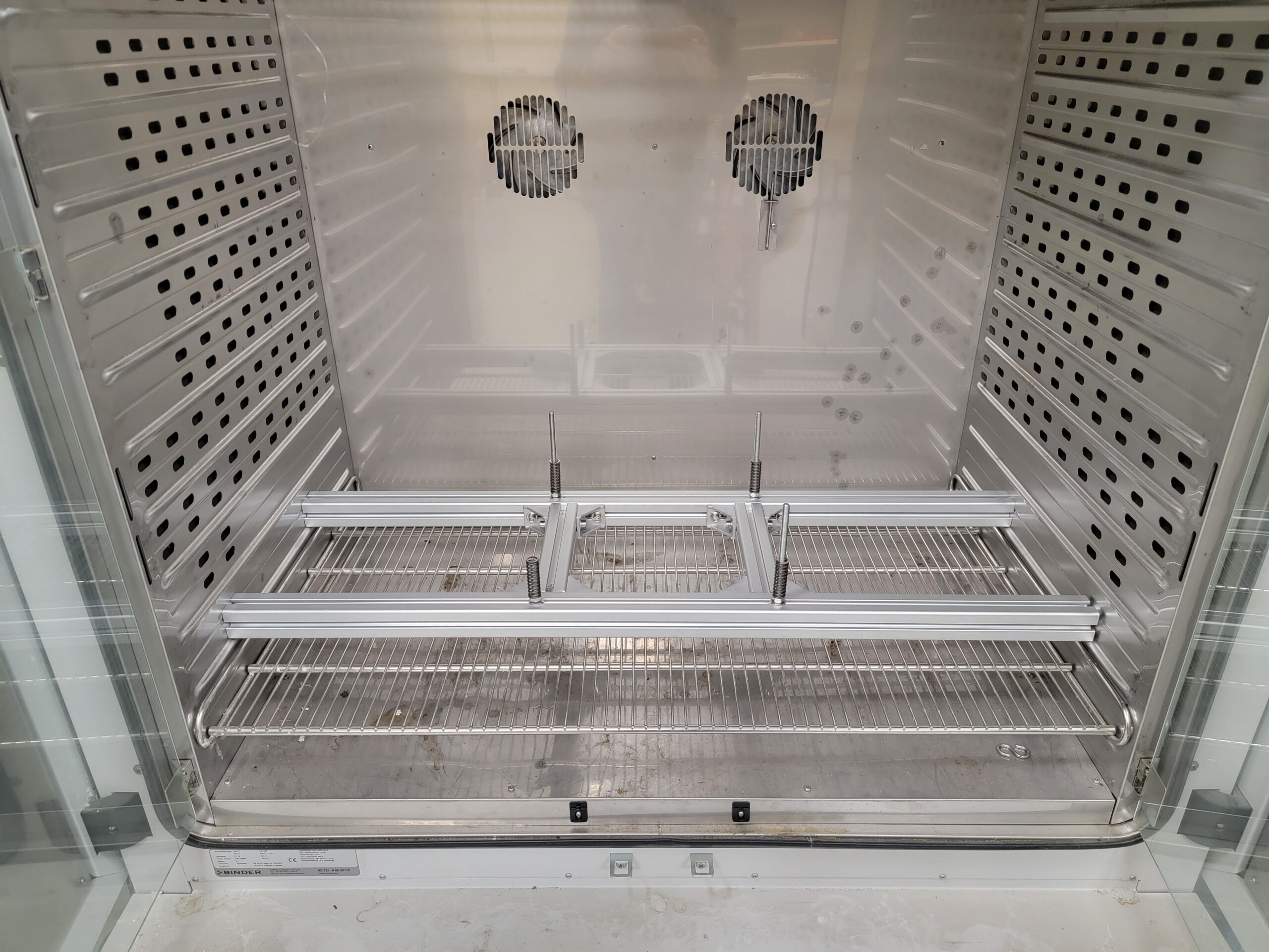
3️⃣ Raise first, second and third floors! 😊
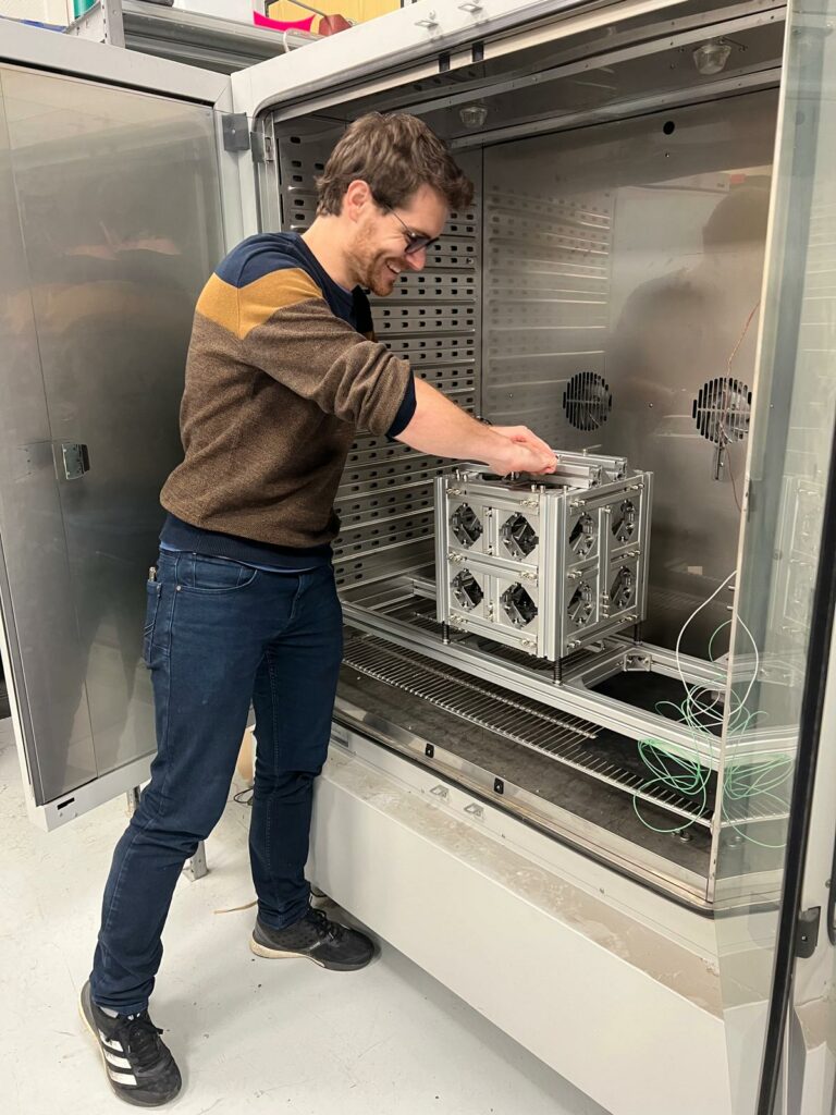
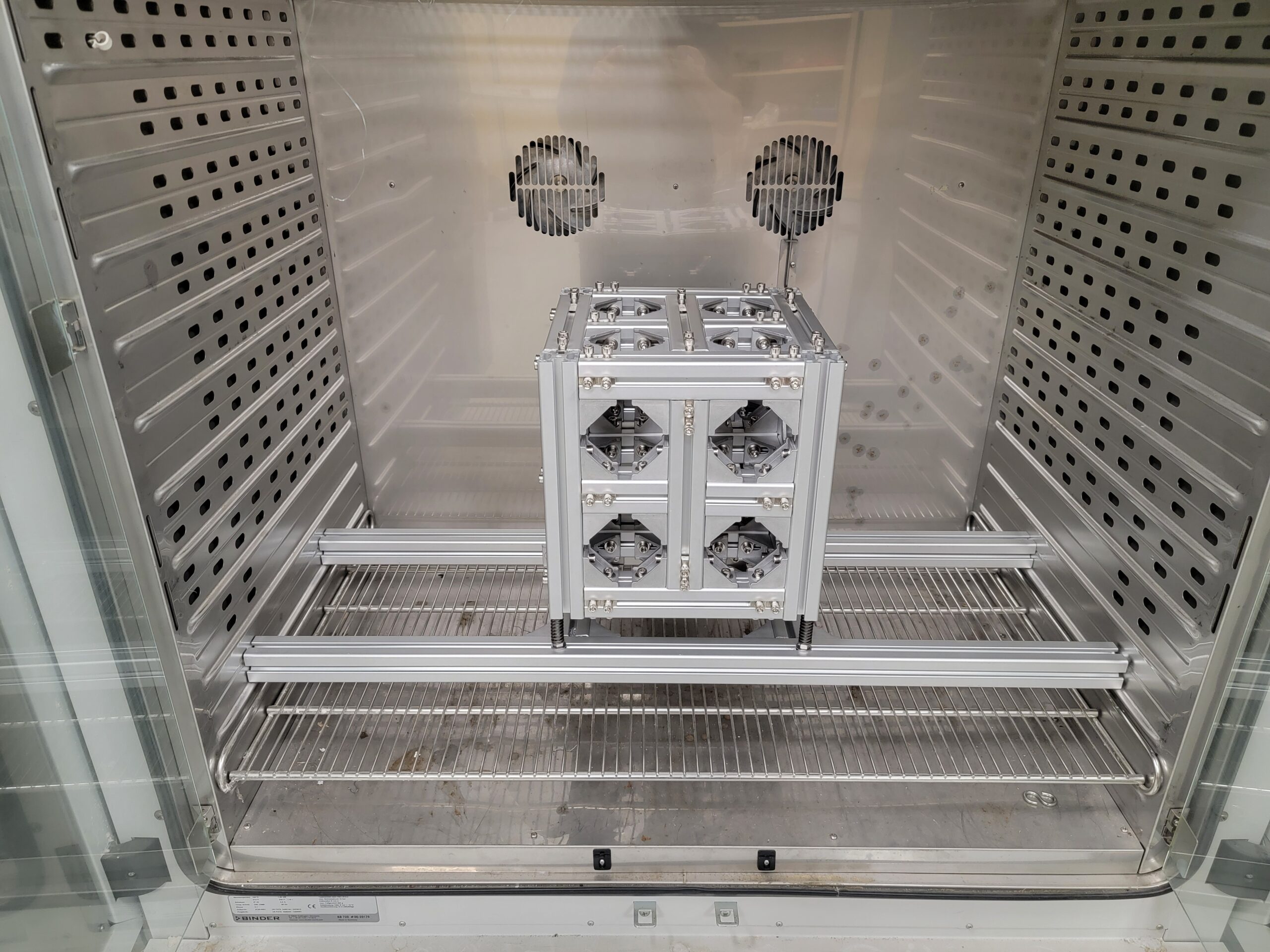
4️⃣ Put the suspension frame, the cube, the training weights, and the system into the oven.
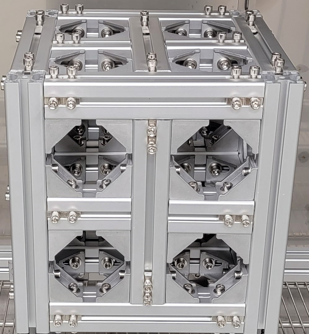
III Conclusions
We are now happy to physically see our “hypercube” base!
It is customizable
- Weight from 20kg to 100kg
- Fasteners to fit any system on top
- Fasteners to fit a suspension device at the bottom
- Fasteners to further evolution on each side of the cube.
The next step is to validate the realized system regarding the initial specifications. The critical question is whether the prototype actually dynamically behaves as the (maybe too 😉) coarse model. The unknown mostly resides in beam connections. Are nodal equivalence constraints at beam ends representative of the bolted 90° bracket connection stiffness? The assumption only has to be valid for the first mode at low amplitudes!
Only measurements will tell! But this is another story… 😏