PDF Index
| SDT-piezo
Contents
Functions
PDF Index |
The example below illustrates the general definition of actuators and sensors which are not collocated.
In  d_piezo('TutoPzBeamNCol-s1')
), the mesh is created and two point sensors are defined as 104-x and 207-y (Figure 4.8)
d_piezo('TutoPzBeamNCol-s1')
), the mesh is created and two point sensors are defined as 104-x and 207-y (Figure 4.8)
Then in d_piezo('TutoPzBeamNCol-s2')
, two actuators are defined by combination of three forces (207-x, 241-x and 207-y). The first actuator consists in two forces on nodes 207 and 241 in opposite direction along x acting together, and the third force is on 207-y.
%% Step 2 : Define point actuators
% relative force between DOFs 207x and 241x and one point loads at DOFs 207y
data  = struct('DOF',[207.01;241.01;207.02],'def',[1 0;-1 0;0 1]);
model=fe_case(model,'DofLoad','Actuators',data); %
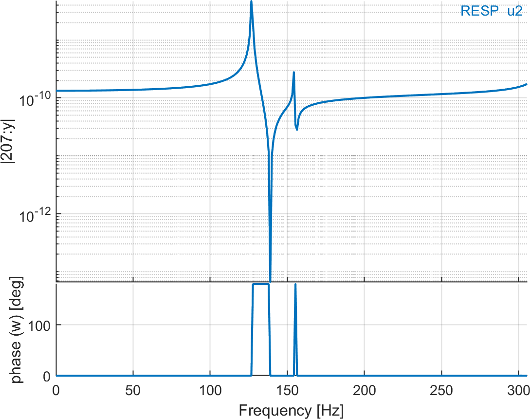
In d_piezo('TutoPzBeamNCol-s3')
and (d_piezo('TutoPzBeamNCol-s4')
), the static and dynamic responses to these loads are computed and represented in Figure 4.10 and Figure 4.11.


.png)
.png)