
♻️Refreshing of our good old logo is an occasion to illustrate SDT’s display capabilities in FEM, testing and hybrid twins handling.
💡Our logo features the first ever structure that was simulated in what was to become the SDT. It is a tetrahedron shaped truss working as a mirror support in satellites that was studied by Etienne Balmes during his PhD. Its particular interest was to feature modes with high multiplicity for which traditional modal identification methods were not enough regarding the accuracy needed to control optical grade mirror orientation under vibrations.
👀🔙⌛The original FE model having been lost; the first fun part was to go back diving into Etienne Balmes’ thesis written in 1993 to find the structure’s characteristics. For the most curious among you, you can find it on Etienne’s ResearchGate page: https://www.researchgate.net/publication/38003114_Experimentalanalytical_predictive_models_of_damped_structural_dynamics
✨Then we generated a modern version of the truss and played with display variations to obtain a new visual.
In the following we will show how this was entirely done in SDT, to highlight its capabilities in FEM, test and hybrid model handling through definition and display strategies:
👉 Building a FEM mesh and computing modes
👉 Building a test mesh and its associated model observation
👉 Animating FEM and test together
👉 Illustrating FEM, Test and hybrid twin all at once
Building a FEM mesh and computing modes
To illustrate FEM capabilities, the idea is to animate a mode shape of the SDT logo source FEM.
We have a tetrahedron shaped truss, so to build the model, we are going to exploit all its symmetries.
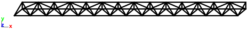
The first step is to position the nodes and beam elements making up the elementary truss cell.
>> feutil AddNode
>> feutil AddElt
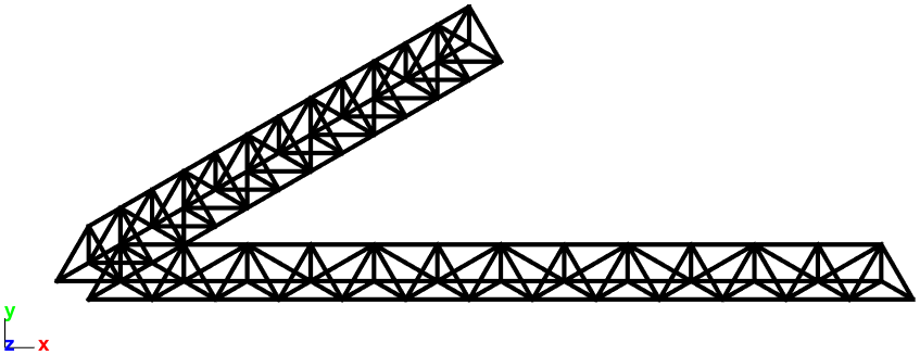
This cell is repeated 6 times to form an edge of the overall tetrahedron.
>> feutil RepeatSel
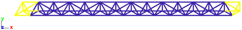
And some undesired elements at both ends are removed (yellow elements below)
>> feutil RemoveElt
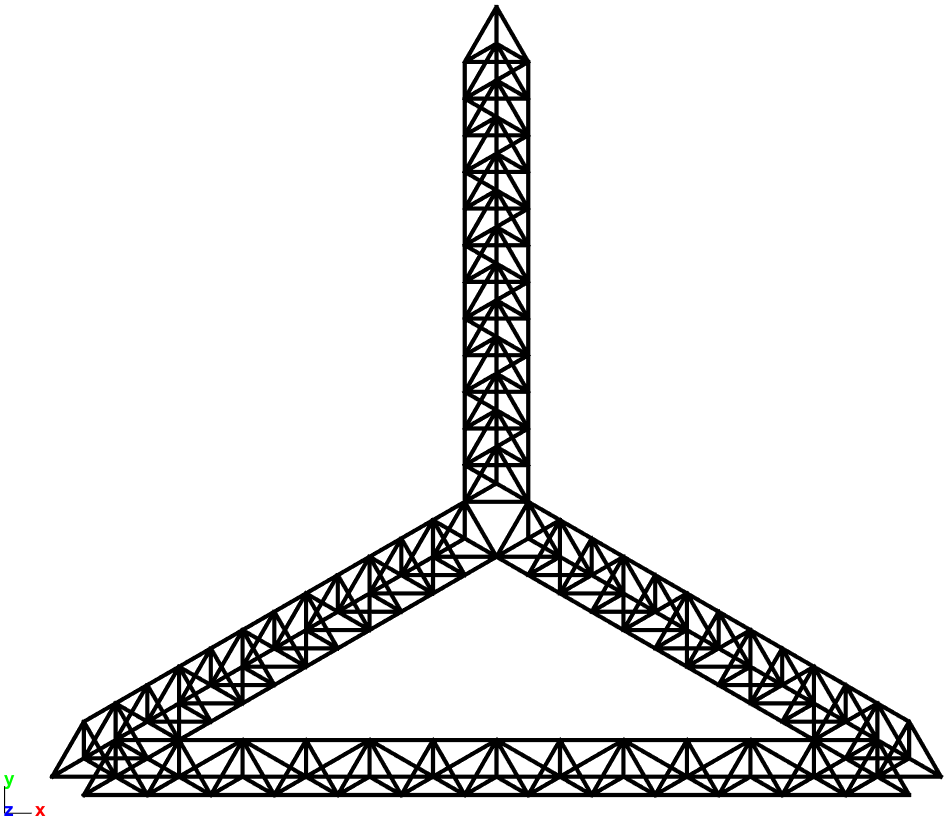
Cell repetitions through rotation symmetries are then performed:
- First: repeat cell after 120° around the first symmetry axis
- Second: repeat cell after 120° around the second symmetry axis
- Third: repeat cell after 240° around the second symmetry axis
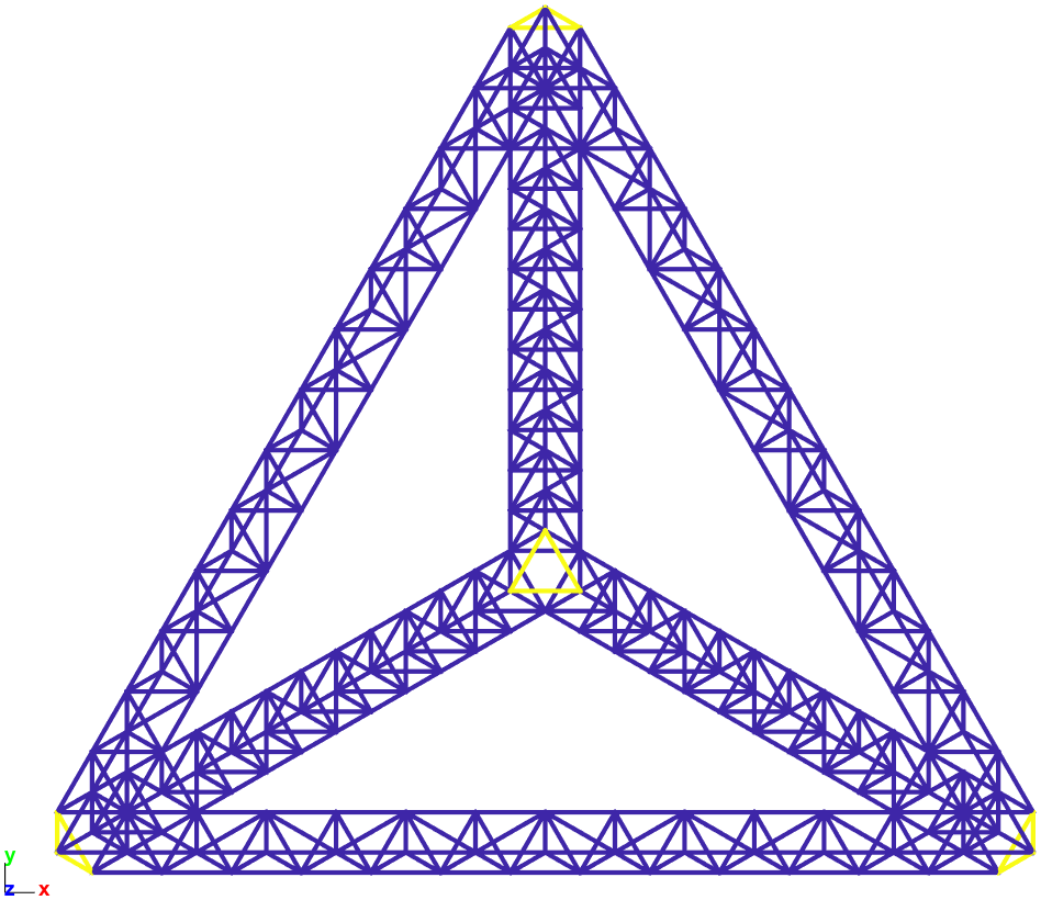
The 4 main corners are then closed with three beams for each one (yellow elements below) to obtain the final mesh
>> feutil AddElt
Once the mesh is done, we need to assign beam elements properties:
- material law (aluminum)
>> m_elastic - integration properties (circular section radius 10mm)
>> p_beam
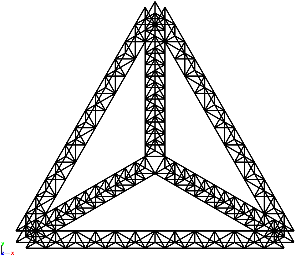
The mode shapes can then be computed and displayed.
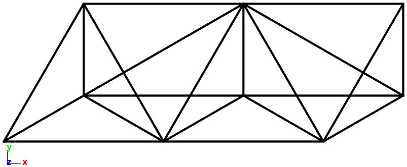
The 10th mode animated below corresponds to the SDT logo 😊
Building a test mesh and its associated model observation
To illustrate testing capabilities, we want to animate a test frame based on the model.
7 triax sensors will be placed on each edge of the overall tetrahedron. Exploiting the same symmetries, the following test wireframe has been created.
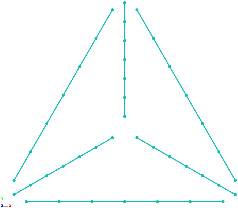
The tri-axes sensors are placed at each node of the wireframe
>> Sensor and wireframe geometry definition formats
and the observation matrix of the FEM through sensors is built
>> Topology correlation and observation matrix
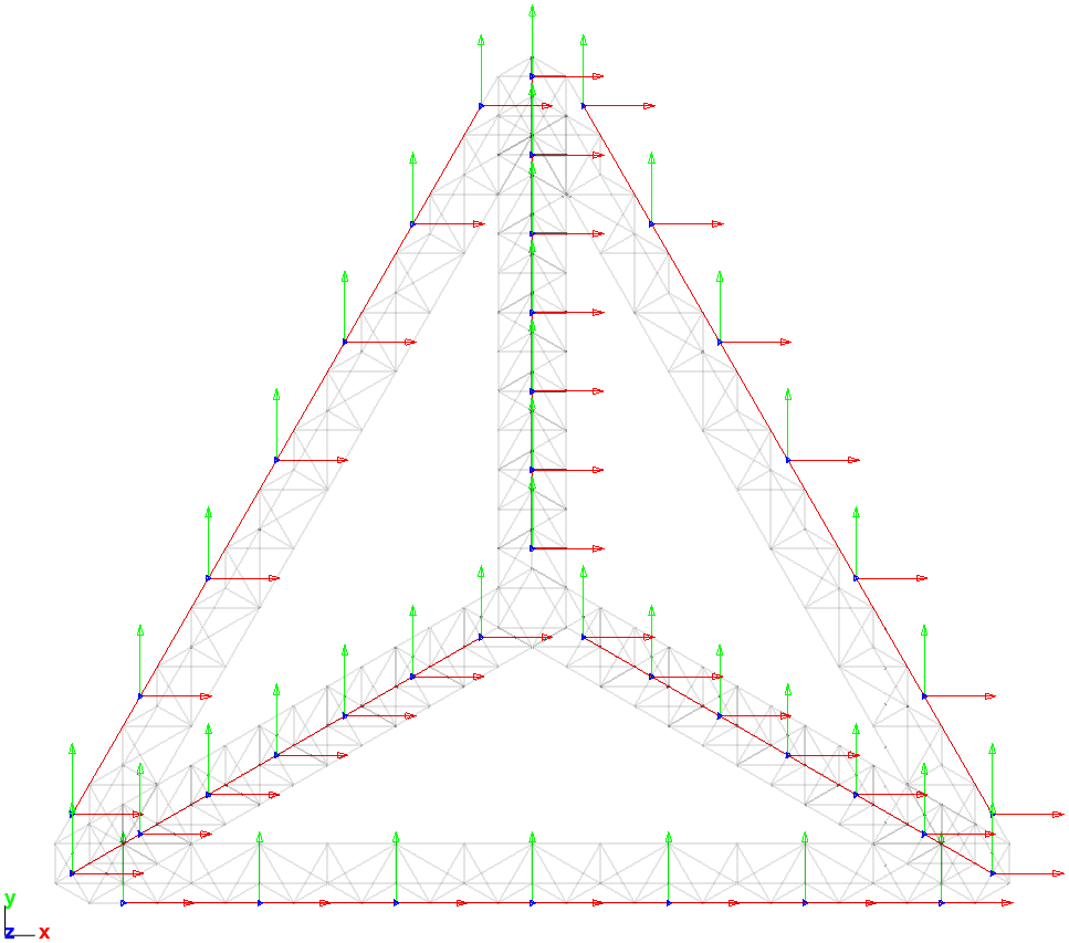
The mode shape can thus be observed at sensors (location and direction) and the animation on the test wireframe is displayed below.
Animating FEM and test together
The two previous animations illustrate FEM and testing capabilities of SDT.
The last topic to highlight is hybrid twin (Test/FEM correlation) where both the FEM and the test are used together, either for correlation purpose or coupled methods. Displaying overlayed FEM and test frame geometries then becomes very useful.
To obtain an exploitable view, we want to animate the FEM with thinner beam element display and a bit of transparency on top of which the test wireframe is animated without coloring.
Illustrating FEM, Test and hybrid twin all at once
To illustrate the three capabilities and the complementarity in the same figure, a customized display combining three selections of elements are defined using the following planes.
>> fecom Sel
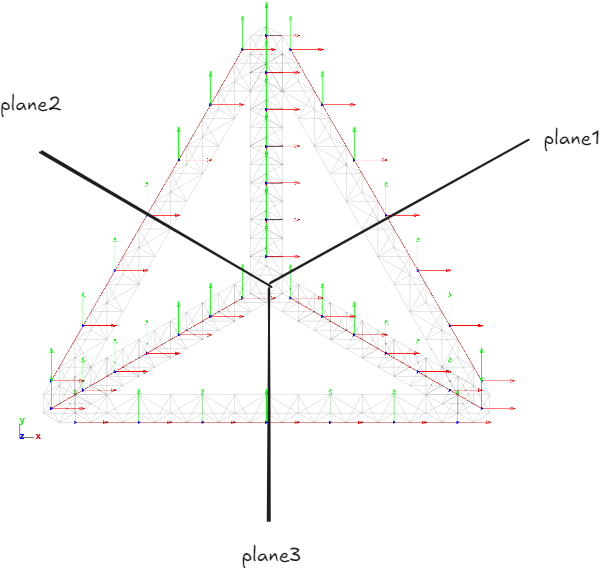
For each selection, the properties of the display object are defined:
- Bottom right selection animates the FEM mode
- Bottom left selection animates observation of the mode at sensors
- Top selection animates both the FEM and the test illustrating hybrid twin

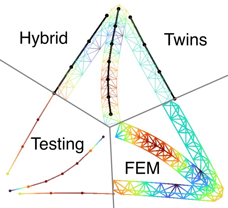
And here we are!
Our tetrahedron truss logo is now hybridized combining various configurations from modeling and testing!