
How to properly manage connections to shells in 3D models ?
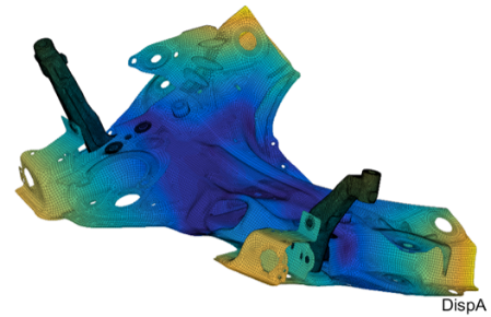
Many mechanical systems use thin structures such as stamped metal sheets for components. This is the case for example in car bodies. Costs for mass production are low, weight is contained, with a good design revision flexibility. Modelling such parts with finite elements can also be optimized using shell elements. Due to the existence of a thin direction, 3D meshing approaches would require to choose a characteristic length compliant to the lowest scale that would generate numerous elements, whereas ignoring the lowest direction would generate distorted meshes. Both 3D meshing approaches are thus commonly unacceptable for computation time or quality reasons.
The shell elements directly integrate the thin dimension, assuming a linear displacement field through the thickness. While adding rotational degrees of freedom at node control section deformation, the small direction disappears from the mesh and larger characteristic lengths can be used. Nowadays, meshing processors can estimate the local thickness and generate a midplane section pretty well from a CAD topology.
The shell mesh simplification however has some drawbacks when it comes to generating connections such as weld spots or beads, fasteners or contact.
- How to take into account shell thickness in connections ?
👉 Rigid link between shell and node at the shell surface - How to ease connections to the shell surface ?
👉 Work with the shell skin topology - How to manage small connections in comparison with the characteristic mesh size ?
👉 Local shell mesh refinement
Shells connections: account for the shell thickness
As the shell mesh only considers the reference plane, the surface skin itself is not present. For simple cases one can work with an offset reference plane on the connection side, but that solution is far from general. In practice one has to account for the shell thickness offset as a force applied to the skin will induce a moment to the connected nodes of the reference plane through the shell section. Accounting for that offset is critical to ensure a proper behavior.
In SDT, connections to shell elements can account for offsets as a post-treatment of the matching procedures in feutilb MpcFromMatch (https://www.sdtools.com/help68/feutilb.html#MpcFromMatch). The matching procedure defines the projection on the shell of the node to connect. The MPC generation then estimates the displacement constraint on the projected node using the shape functions and assumes a rigid link between the point and its projection on the shell.
Working with the shell skin topology
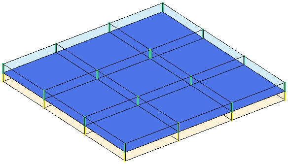
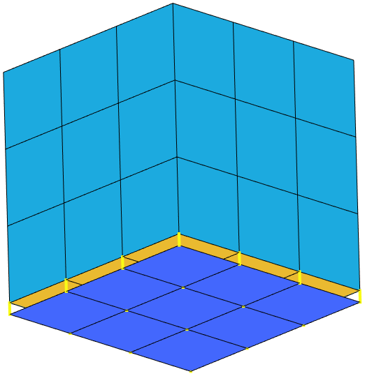
This low-level feature allows direct connections to be established, but it remains limited for complex cases (multi materials, stack of shells, bolts….). The solution is then to use the skin topology to define the connections with physical locations and use rigid links between the connection points on the skin and the reference plane This is realized in SDT with command ShellSkin ( https://www.sdtools.com/help/nl_mesh.html#ShellSkin). Shell elements are extracted and extrusions along the shell normal are performed to obtain various skin meshes
- Shell skin mesh with rigid links to the original nodes.
- Volume mesh.
- Volume mesh with rigid links to the original nodes.
After connections are defined using ShellSkin strategy, the user can keep the skin nodes of interest and the associated rigid links to the original shell elements. For contact element generation, this is automated when slave or masters are based on shell elements. Contact elements are then created at skin location. For slave selections, a skin visualization mesh is generated for display.
For more generic constraints the rigid connections can be directly integrated in the equations to avoid additional element in the model. In the same manner, a coupling superelement with the rigid elements and the coupling constraints can be setup to maintain editability.
Local shell mesh refinement
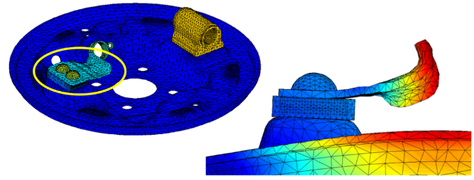
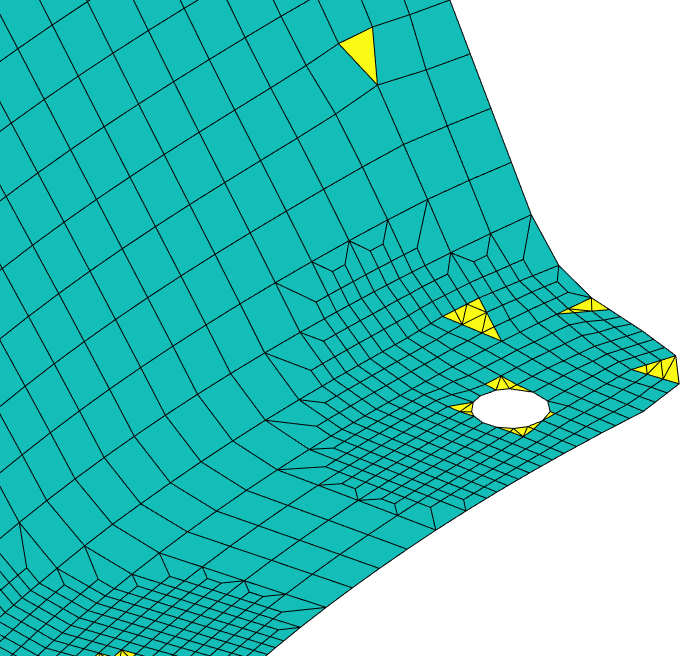
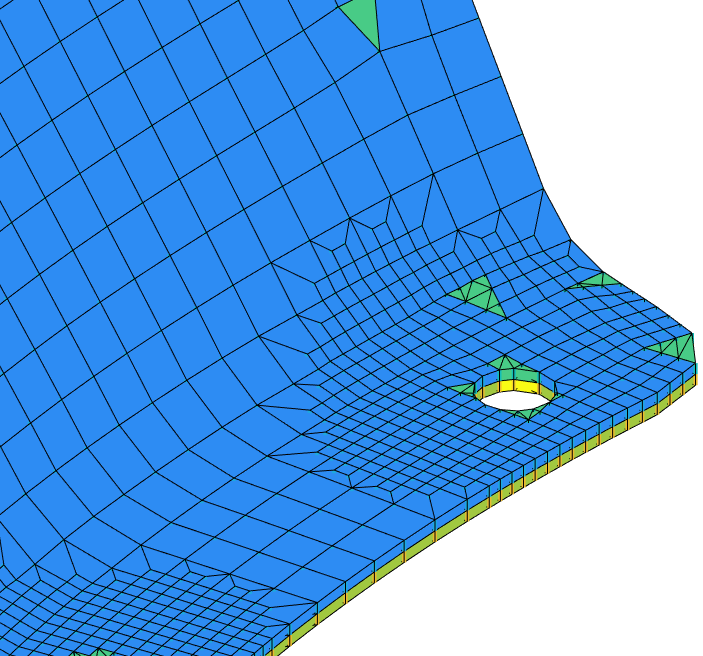
As interface scales are smaller than volumes, it is common that shell meshes for large models feature inadequate characteristic mesh length for fasteners. A classic example concerns electric weld spots in the automotive industry [1]. They are usually quite small in diameter, so that the application area on the shell requires some local refinement. This is especially the case when a hole should be drilled to keep the weld spot material as a beam with connections to the shell.
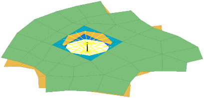
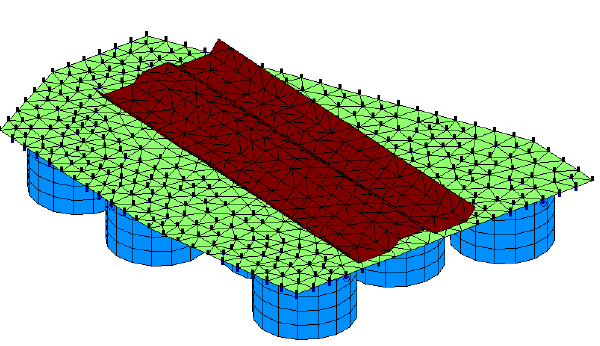
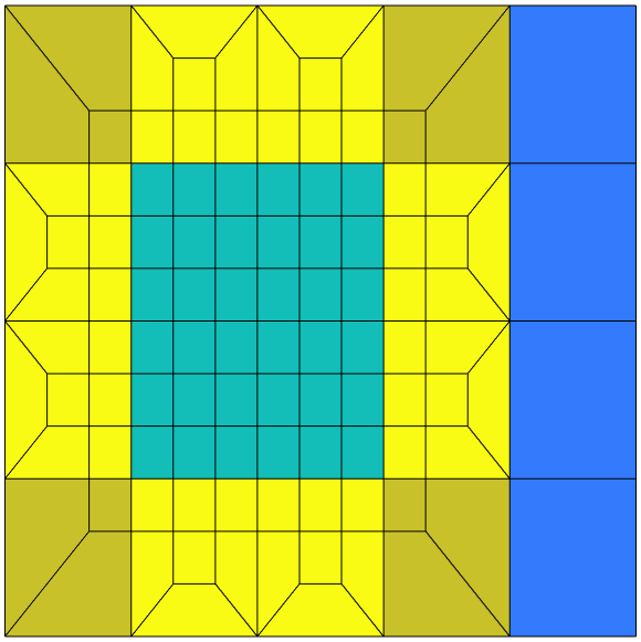
SDT provides a local 3:1 refinement strategy for quad meshes with command fe_shapeoptim RefineQuadSurf. For a given selection of elements on an arbitrary quad mesh, a 3:1 refinement is performed while keeping a compatible mesh with the remaining model. The refined area can then be set to the fastener scale for further treatment.
As modern meshers allow triangle inclusions in their output (quadrangle dominant solutions as seen in GMSH or ANSA). The implemented methodology supports such mesh by applying the associated refinements to the triangles.

Conclusion
Shell elements are very common in industrial applications to model shallow structures. Their use requires some care when dealing with connections in 3D assemblies as the thickness has to be accounted for to describe the forces applied to skins of the components meshed as shells. Various solutions are given in SDT to allow proper modelling using skin mesh topologies and ad hoc mesh refinement for small fasteners.
References
[1] Error localization and updating of junction properties for an engine cradle model
G. Vermot des Roches, E. Balmes, S. Nacivet
ISMA 2016
[2] Updating and design sensitivity processes applied to drum brake squeal analysis
G. Martin, E. Balmes, G. Vermot des Roches, T. Chancelier
Eurobrake 2016
[3] Reduced order brake models to study the effect of squeal of pad redesign
Vermot des Roches, Guillaume, Balmes, Etienne, Chiello, Olivier, Lorang, Xavier,
Eurobrake 2013