
How do you handle simplified connections in a Finite Element model with control on accuracy ?
Modern simulation capabilities allow considering very large finite element models, including mechanical assemblies. They require interaction models between components, that can be seen as interface connections (junctions, fasteners, contact support…). A major challenge is the change of scale between components and their interface. There, local behavior can be critical to the overall response.
High fidelity modelling would consider all 3D parts to be meshed, with contact/friction interactions in between. It is however common to resort to connection simplifications to control model size and convergence, while complying to simulation objectives. The transition to simplified connections is then implemented using Multiple Point Constraints (MPC) that define displacement/force transmission.
MPC is broadly used in industrial applications and readily available in simulation tools. But despite an apparent ease to use, its correct implementation is not that straightforward:
- many MPC types exist
- their usage comes with some implementation challenges we must be aware of
- MPC penalization is sometimes required for tuning
This post presents common MPC implementation strategies, warnings and some insights on their integration and manipulation in SDT.
MPC in common applications
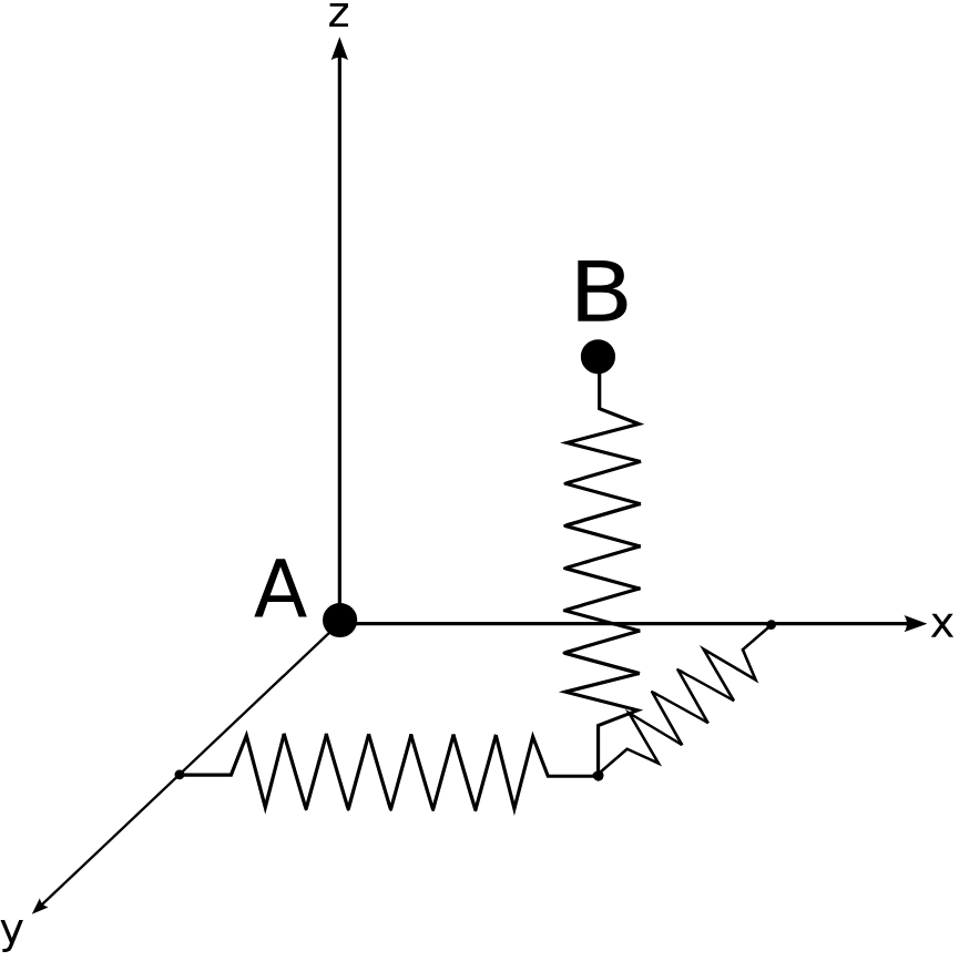
Classical fasteners or connectors include bolts, screws and articulation mechanisms. It is usual to resort to simplified 0D or 1D models for these mechanisms, to render the proper mass, stiffness, damping and kinematics associated to the connection. Screws are thus modelled using beam elements, and more complicated connectors can use spring-like elements to implement constraints or stiffnesses for each direction. In SDT celas and cbush (https://www.sdtools.com/help/celas.html) elements provide a topology for such connectors, including the ability to implement non-linear constitutive behavior.
These so-called structural elements still require to be linked to the parts they are connecting. The link has to transfer displacement and loads to the connected parts. It is realized by multiple point constraints (MPC) that describe the relation between selected parts DOF and the structural element nodes.
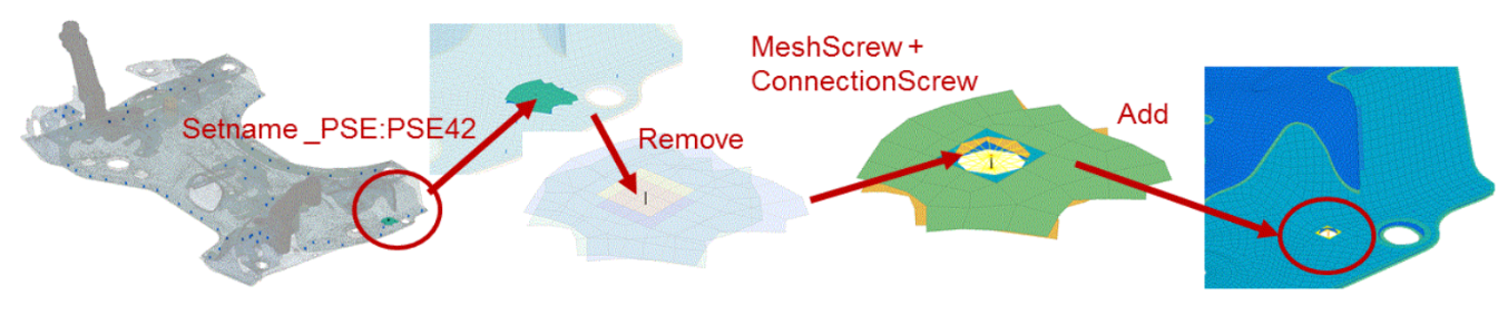
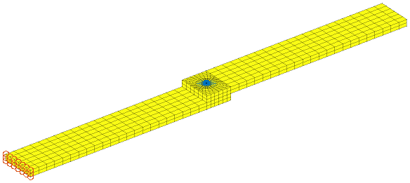
For automotive body in white structures, many weld spots and other beads are used for assembly. Resorting to a 3D model for these connections would be very costly and difficult regarding material property definitions. For electric weld spots, a beam replaces the welded area and an MPC connection links the spot to the main structure. For [1] an automated procedure to generate weld spot models has been implemented in SDT, based on spot cylinders to cut the mesh, and generate the connection.
Model lumping using structural elements is also possible, using calibration [2]. Numerical calibration for bolted joint models comes with a high-fidelity flange modeling and several levels of bolt refinement can be devised [3].
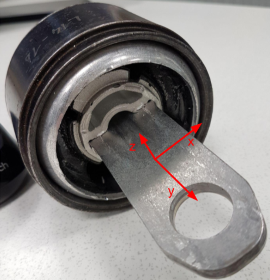
The connection can be significantly non-linear as for rubber mounts. Different modeling levels can be implemented depending on the need as discussed in [4].
MPC types and definition
At low level, the implementation is direct relationship equations constraining some displacement DOF to be a linear combination of others. The constrained DOF are then named slave as they become redundant, completely defined by the master DOF displacement. More information can be found in our documentation https://www.sdtools.com/help/mpc.html#mpc.
For standard applications, MPC types have been defined to allow higher level definitions.
- Rigid links forcing equal displacements or rotation between a master DOF and possibly several slave DOF are called rigid in SDT, RBE2 in NASTRAN, Kinematic coupling ot BEAM type MPC in ABAQUS and correspond to specific keyopts of MPC184 in ANSYS. These links are common to transmit displacements through simplified fasteners. When it is distributed on a surface the whole slave DOF set behaves rigidly, generating a stiff connection.
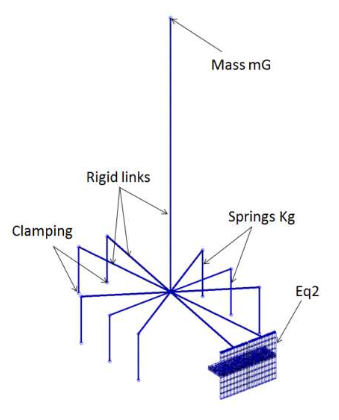
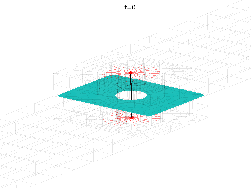
- RBE3 links are designed to transmit forces, and constraints specific slave DOF displacement to be the average of a selection of master DOF. This link is called RBE3 in SDT and NASTRAN, Distributed coupling in ABAQUS, and specific configurations of CONTA174 in ANSYS. As movement is imposed on average, the connection is softer, and can be useful for actuators simplifications.
- Surface bonding is another common feature. The MPC objective is here to constrain the relative movement of two surfaces together, one being specified as slave and one as master. The constraint can be seen as a fixed contact/friction formulation. These constraints are defined in SDT using ConnectionSurface (https://www.sdtools.com/help/fe_case.html#ConnectionSurface, surface to surface formulation), TIE in ABAQUS, CONTA174 or CONTA175 in ANSYS, CONTACT keys in MSC.Marc. It is also possible to use zero thickness elements (see our related post with flange contact modeling) for this purpose.
- Many other formats can be defined, see https://www.sdtools.com/help/fe_case.html. In particular SDT provides an integrated Screw type connection definition. ABAQUS also provides many MPC types, that are translated in SDT using cbush elements.
In practice any integration becomes resolved into a generic set of constraint equations. It is possible in SDT to recover the resolution separately (https://www.sdtools.com/help/mpc.html#sec270).
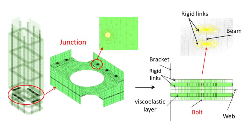
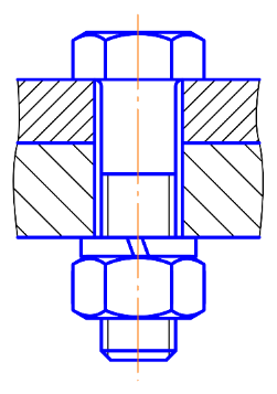
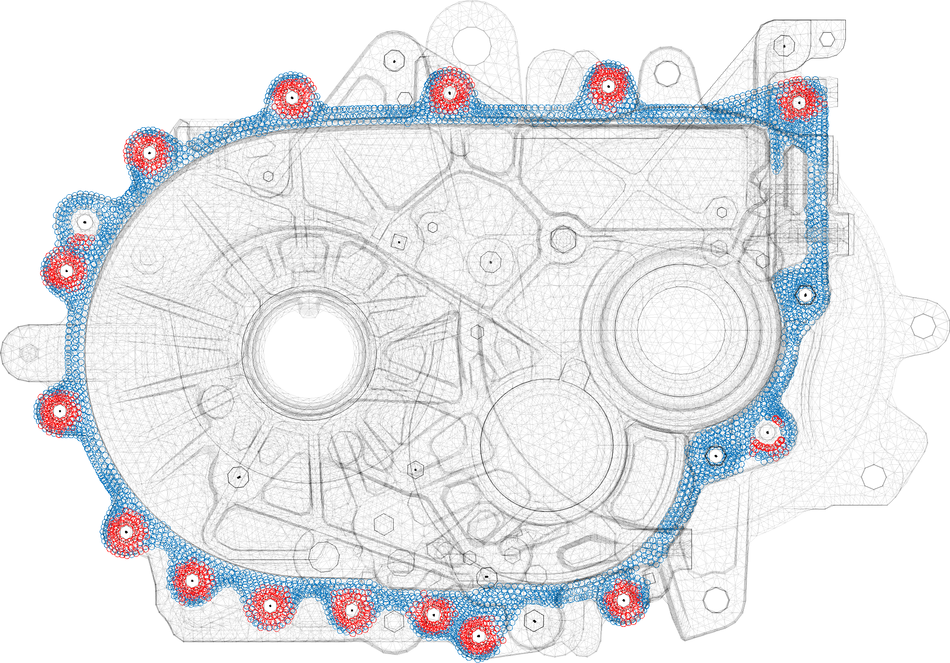
A single connection can require several features. For bolted connections, the bolt is often simplified using beam elements and neglecting the head and nut – the missing mass can be added with mass elements. The head and nut side coupling are then realized with rigid links or RBE3 rings applied along the head and nut radii. Flange connection is another concern. Realistic coupling such as in [3] would use surface connection features between the flanges. Meta modeling or coarser representation will use central cbush elements to directly connect to the central beam.
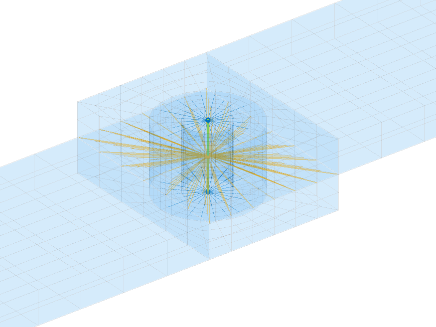
In practice, non-linear bolt loading usually show a pressure area under the bolt, so that it is useful to distinguish between a stiff minimal coupling surface and a larger surface of lower stiffness, such as the example below.
Challenges associated to MPC
As the connection operates between different scales, formulations and possibly non-conforming meshes, their definition may come with some issues.
- Risk of locking when matching incompatible interfaces, over-stiffening when the distribution covers large portions of a system.
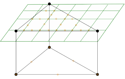
In the example below surface bonding will be problematic. If the green surface is master an over-constraint will be applied to the coarser slave due to the numerous points: only a rigid movement will be compatible. If the coarse surface is master some elements in the green surface will not be constrained. Regularization methods exist [5,6].
- Slave multiplicity is not possible in practice as it leads to over-constraints. Some codes try to avoid errors by internally reprocessing MPC, but with no results guaranteed. Mitigation is possible by linking intermediate nodes with stiff springs.
- Sometimes bonding also has some flexibility that should be accounted for. It is the case for contact applications, or bonding with materials for example.
MPC Penalization or functional representation
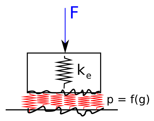
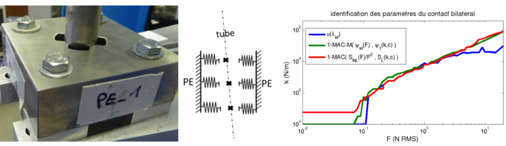
For these matters, penalization is a solution that balances the constraint by instead applying a force opposing the constraint violation. This is also called dual formulation, or weakly enforced constraint. The force proportionality is homogenous to a stiffness coefficient and can be tuned to fit the objective. It can be for accuracy in terms of displacement convergences, but also in terms of correlation, when a physical meaning can be given to the penalization coefficient [7,8,9]. The following example from [8] illustrates how a given flexible support stiffness can be identified as function of its operating regime.
Other benefits concern over-constraint release as no direct slave DOF gets eliminated anymore. Better conditioning can be obtained for specific models, and numerical studies can be run to assess the model sensitivity to these types of connections.
In SDT it is possible to convert any constraint into its penalized form using CaseC2SE command https://www.sdtools.com/help/feutilb.html#CaseC2SE. The penalized form is packaged into a coupling superelement. Stiffness factors are defined automatically if no value is specified. Parametrization for sensitivity studies will be detailed in further posts.
Conclusion
To conclude this post, coupling modeling for mechanical assemblies come in many forms depending on the application objective. Simplification is classical to maintain balance between accuracy and model size. Transition between high fidelity and simplified areas often require the use of MPC whose definition strategies and shortcomings have been presented. The ability to convert and adapt MPC for model quality improvement is then critical. In a next post we will focus on verification methods associated to coupling features in assemblies.
References
[1] Error localization and updating of junction properties for an engine cradle model.
G. Vermot des Roches, E. Balmes, S. Nacivet (ISMA 2016)
https://sam.ensam.eu/handle/10985/11294
[2] Reduced joint models for damping design of multi-jointed structures
Hammami, Chaima, Etienne Balmès, and Mikhail Guskov, (VISHNO 2014)
https://sam.ensam.eu/handle/10985/8597
[3] Numerical design and test on an assembled structure of a bolted joint with viscoelastic damping.
C. Hammami, E. Balmes, M. Guskov (MSSP 2015)
http://hdl.handle.net/10985/10455
[4] Hyper-reduced models of hyperelastic dissipative elastomer bushings. Rafael Penas, Arnaud Gaudin, Etienne Balmes (ISMA2020)
https://hal.science/hal-03980065/
[5] Use of Generalized Interface Degrees of Freedom in Component Mode Synthesis.
Etienne Balmes (IMAC 1996)
https://sdtools.com/pdf/IMAC96int.pdf
[6] Compatibility measure and penalized contact resolution for incompatible interfaces
G. Vermot des Roches, E. Balmes, H. Ben Dhia, R. Lemaire (EJCM 2010)
https://hal.science/hal-00987025
[7] Benchmarking Signorini and exponential contact laws for an industrial train brake squeal application
G. Vermot des Roches, O. Chiello, E. Balmes, X. Lorang. (ISMA 2012)
https://sdtools.com/pdf/isma12_ContactBench.pdf
[8] Definition of a linear equivalent model for a non-linear system with impacts.
T. Thénint, E. Balmes, M. Corus (ISMA 2012)
https://sdtools.com/pdf/isma12_nlvib.pdf
[9] Updating and design sensitivity processes applied to drum brake squeal analysis.
G. Martin, E. Balmes, G. Vermot des Roches, T. Chancelier (Eurobrake 2016)
https://sam.ensam.eu/handle/10985/10922